Water Treatment & Sludge Dewatering
COLUMN 04Lamella Clarifier Selection: Surface Loading, Solids Loading & Sludge Balance
Sedimentation separation using inclined pipes was evaluated from both the water volume and SS load. We will explain flow rate fluctuations, coagulation conditions, and capacity matching with post-stage dewatering.
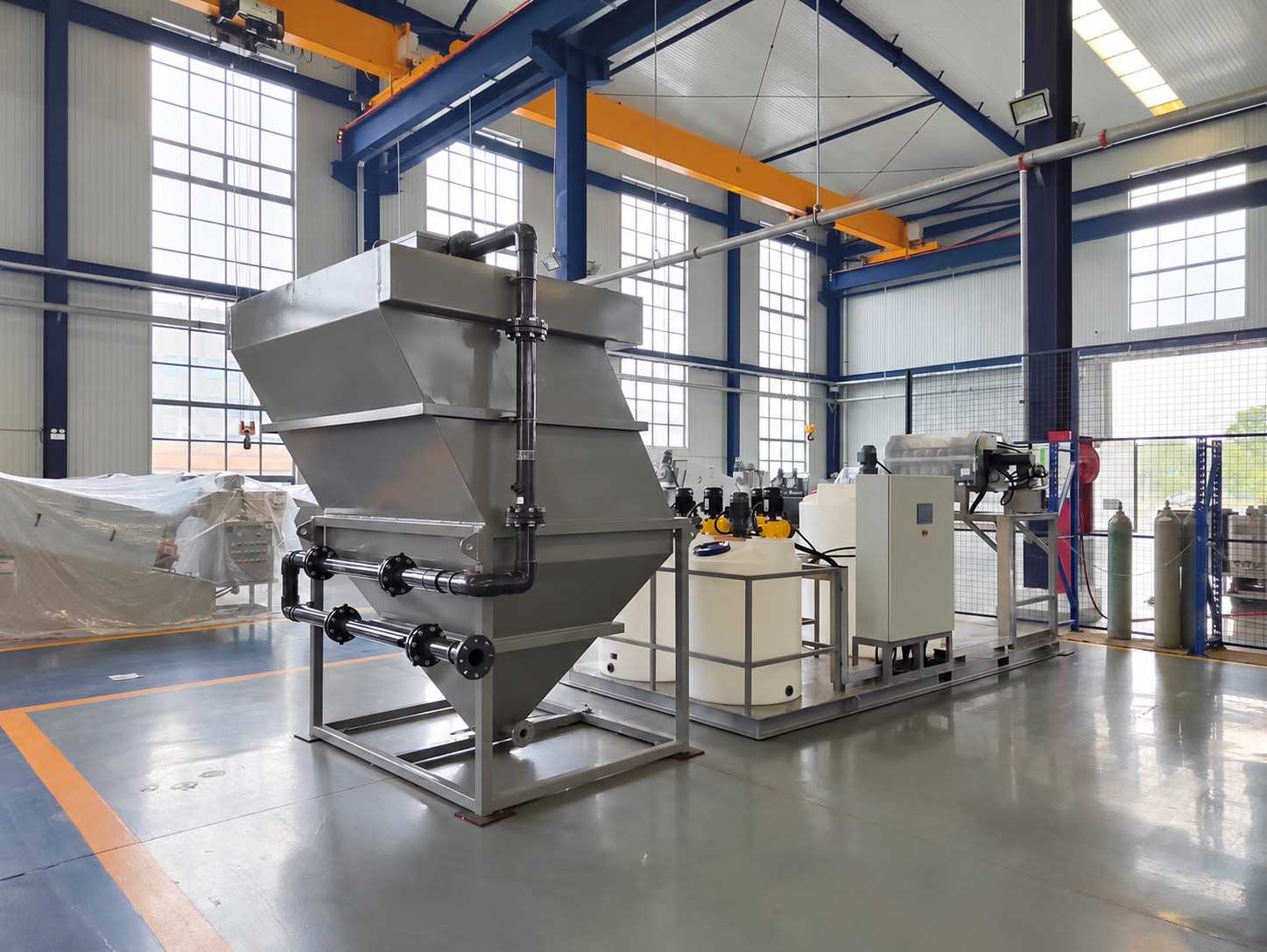
Selecting a lamella clarifier requires more than a flow rating in m³/h: particle settleability and hourly solids loading must also be assessed. Inclined tubes provide additional settling area, but uneven flow or inadequate sludge removal can prevent sustained separation. This article focuses on the inclined-tube equipment we offer and the criteria needed to match it to upstream and downstream processes.
Contents of this article
- 01Equipment that separates sedimented suspended matter from water
- 02Inclined tube secures area for sedimentation separation
- 03Whether flocculation is necessary is determined based on the properties of the raw water.
- 04Plan the respective outlets for treated water and sludge
- 05Check water area load and SS load separately
- 06Choose by considering not only the amount of water but also cleaning and inspection.
01Equipment that separates sedimented suspended matter from water
Fine solids dispersed in water are known as suspended solids; SS is used to express their concentration. A lamella clarifier separates settleable suspended solids into clarified water and settled sludge. It may be considered for solids-bearing wastewater from stone, ceramic and glass processing, among other applications.
Dissolved substances and particles that do not settle readily cannot all be removed in the same way. The treatment required depends on the wastewater composition and settling characteristics. Confirm the actual influent and target water quality rather than selecting equipment from the application name alone.
02Inclined tube secures area for sedimentation separation
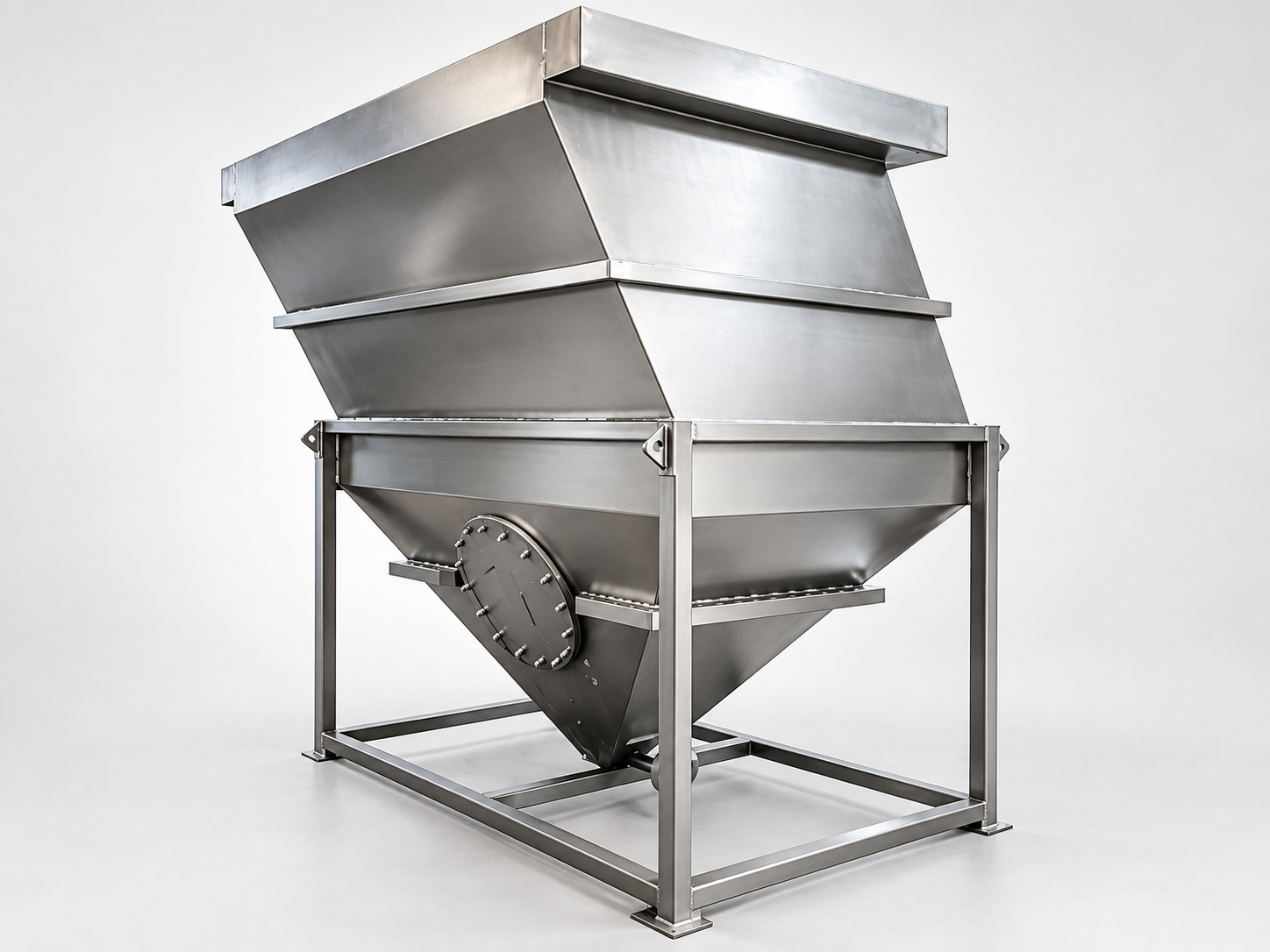
A bank of inclined tubes provides settling surfaces within a compact footprint. Influent is distributed through the tank, solids separate in the tube section, and clarified water is collected above. Settled solids collect at the bottom and are discharged as sludge.
External appearance does not reveal the condition of the tube pack or the internal flow pattern. Performance depends on tube arrangement, particle settleability, flow distribution, flow fluctuations and solids loading. Assess conditions for the actual wastewater, rather than relying only on claims of high flow capacity in a small footprint.
03Whether flocculation is necessary is determined based on the properties of the raw water.
Fine particles may not separate effectively by natural settling alone. Chemical flocculation can be considered to form larger, more readily settling particles. Determine whether a flocculant is needed, and its type and dose, from wastewater characteristics and test results rather than a universal setting.
Before selection, gather influent SS concentration, particle size and settling characteristics, pH, oil content and information about process chemicals. If water quality changes during production changeovers, document both normal and variable conditions. Existing settling-tank problems and flocculation test results are also useful.
When sampling, distinguish freshly generated wastewater from water that has stood in a tank. Sampling time and location can change the measured solids concentration and apparent settling behavior. Record the sampling conditions and interpret the results in relation to actual influent conditions.
04Plan the respective outlets for treated water and sludge
Route clarified water to discharge, reuse or further treatment as required. Reduced visible turbidity alone does not establish suitability for reuse. Check the water-quality parameters required by the receiving process and add further treatment where necessary.
Plan sludge removal to suit its characteristics rather than allowing solids to accumulate indefinitely. Match discharge quantity, sludge concentration and discharge frequency to storage and dewatering capacity. With a filter press, account for the difference between clarifier sludge discharge and the press's batch cycle.
05Check water area load and SS load separately
One useful design measure is the surface overflow rate q = Q/A [m³/(m²·h)], where Q is influent flow and A is the effective settling area used in the design. For inclined tubes, confirm the design area from the tube arrangement and horizontal projected area; do not substitute the equipment footprint directly for A.
For ideal discrete-particle settling, the relationship between settling velocity and surface overflow rate helps explain separation. Actual wastewater is also affected by flocculation, hindered settling and uneven flow. Do not derive a definite removal rate from one particle size or a theoretical value alone; verify it through settling tests and design conditions suited to the wastewater.
Incoming solids loading is L = Q × C. At Q = 10 m³/h and SS concentration C = 2 kg/m³, the load is 20 kg/h. If SS doubles at the same flow, solids loading also doubles. Comparing water flow alone can overlook changes in solids accumulation and sludge removal requirements.
Assuming steady operation and 95% solids capture, the example above requires removal of 19 kg-DS/h. At an assumed sludge concentration of 20 kg-DS/m³, average sludge discharge is approximately 0.95 m³/h. These figures illustrate a mass balance and are not performance guarantees. Intermittent discharge can have a different instantaneous flow, so check storage and dewatering acceptance conditions as well.
06Choose by considering not only the amount of water but also cleaning and inspection.
Assess candidate models using average and peak flow, SS concentration, settling characteristics and target water quality. The m³/h ratings in a capacity table help compare flow, but equal flow does not imply equal separation and sludge discharge requirements when solids quantity or properties differ.
Check the footprint and height together with water and sludge piping, inspection access, cleaning and tube-pack removal space. Also review delivery access, tank material, upstream flow equalization and level differences with downstream equipment. Plan the maintenance method during layout design so cleaning remains practical after installation.
KISEI SHOJI can assist with lamella clarifier selection based on the wastewater source, flow and quality, intended use of treated water and downstream sludge handling. If you are combining settling and dewatering, contact us to review the process from inlet to final discharge.
For replacement projects, share current effluent quality, sludge accumulation, cleaning frequency and behavior during higher flows. Rather than simply selecting a larger tank, identify whether the problem lies in inlet distribution, settling, clarified-water collection or sludge discharge. This makes the necessary corrective measures easier to define.
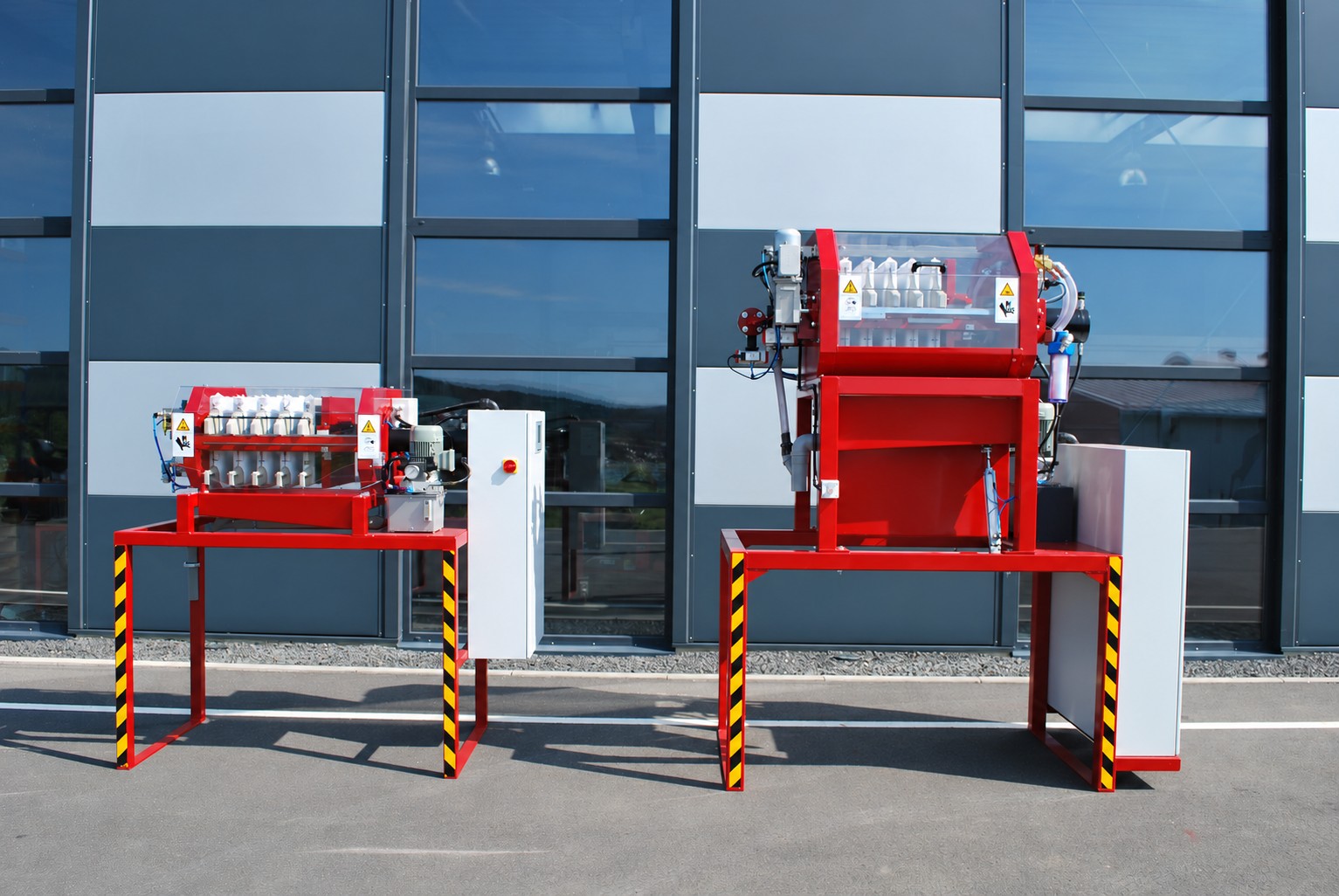
Photos are for reference of appearance and configuration. Partial enlargements are displayed from the same image. It does not indicate individual delivery results or standard delivery scope.