Water Treatment & Sludge Dewatering
COLUMN 03Understanding Filter Press Capacity: Resistance, Chamber Volume & Cycle Design
Understand pressure filtration through filtration resistance, the relationship between chamber volume, daily dry solids throughput and cycle time, and the parameters to verify through testing.
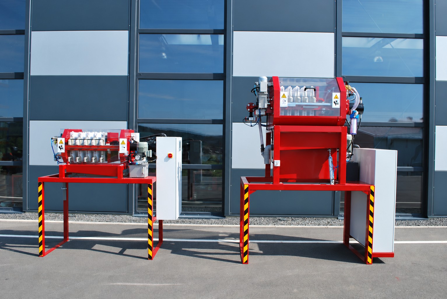
Filter press capacity depends on more than filtration area and chamber volume. Cake filtration resistance, operating pressure and the complete cycle, including cake discharge and cleaning, all affect daily throughput. This article explains pressure filtration and how to assess capacity and define tests for the required duty.
Contents of this article
- 01Filter cloth retains solids and separates moisture
- 02View one processing cycle in four steps
- 03Filtration area and filtration chamber capacity are separate indicators.
- 04Check the condition of the cake and the destination of the filtrate.
- 05Organize filtration speed and daily amount by resistance and cycle
- 06Installation and maintenance space is also a selection criterion.
01Filter cloth retains solids and separates moisture
A filter press feeds sludge into chambers formed by clamped filter plates. Water passes through the filter cloth and is collected as filtrate, while solids remain in the chambers. As filtration continues, the retained solids build up into a dewatered cake.
Filtration is driven by a pressure difference. The equipment name alone does not indicate whether features such as additional membrane squeezing are included. Check the proposed configuration against the required functions, including the feed pump, plates, filter cloth and cleaning system.
02View one processing cycle in four steps
The basic sequence is feeding, filtration and dewatering, cake discharge, then cleaning and preparation for the next cycle. Feed sludge with the plates clamped. After filtration, stop feeding and pressurization, confirm that pressure has been released, and only then open the plates. Discharge the cake and inspect the filter cloth and surrounding equipment before the next cycle.
Filtration is only one part of each cycle. Opening and closing the plates, discharging cake and cleaning also take time. Calculate daily throughput from the complete cycle time and the actual hours available for operation. The level of automation depends on the model and configuration.
03Filtration area and filtration chamber capacity are separate indicators.
Filtration area describes the area available for filtration; chamber volume describes the space available to hold cake. Both are useful selection parameters, but a larger rating does not mean the press can process a proportionally larger quantity of every type of sludge.
Actual throughput varies with feed solids concentration, particle characteristics, filterability, chemical conditioning and cycle conditions. Daily DS throughput is the mass of dry solids processed per day, not sludge volume or wet cake mass. Compare figures only when the sludge characteristics, operating hours and other assumptions are consistent.
Processing a full day's sludge within a short operating window requires different conditions from running over a longer period. Do not size the press from sludge generation alone. The operating plan should also account for available storage, working hours and cake removal frequency.
04Check the condition of the cake and the destination of the filtrate.
Dewatering removes water and prepares the sludge for downstream handling. In addition to cake moisture content, check discharge behavior, adhesion to containers or conveyors, and the requirements of the receiving facility. Published reference moisture contents are not guaranteed for every sludge.
The separated filtrate also needs a defined handling route. Piping and storage requirements depend on whether it returns to the existing wastewater treatment process or is recovered separately. Clear-looking filtrate is not necessarily suitable for direct reuse. Check the required water quality and its composition as part of the overall process.
05Organize filtration speed and daily amount by resistance and cycle
Pressure filtration can be described conceptually by the flux relation J = ΔP/{μ(Rm + Rc)}, where ΔP is the filtration pressure difference, μ is filtrate viscosity, Rm is filter medium resistance and Rc is cake resistance. This is a conceptual cake-filtration relationship, not a capacity equation for an individual model. Resistance changes as the cake builds up.
Higher pressure does not necessarily produce a proportional increase in throughput. Compressible cakes may develop greater resistance under pressure. Test the actual sludge and record filtrate volume over time, cake moisture and cake release behavior rather than judging by feed pressure alone. Additional membrane squeezing is a separate stage available only on suitably configured models.
Daily dry solids throughput equals the DS recovered per cycle multiplied by the number of cycles that can actually be completed. Depending on the configuration, total cycle time includes feeding, filtration, depressurization, plate opening, cake discharge, washing and plate closing. Considering only filtration-time savings can overstate the improvement in daily capacity.
Chamber volume is the space occupied by cake, while daily DS throughput is a mass of dry solids. Converting between them requires cake moisture content, bulk density and filling conditions. Compare tests at consistent feed concentration, chemical conditioning, pressure profiles and stage times, and verify that the cake forms properly and the chambers are adequately filled.
06Installation and maintenance space is also a selection criterion.
Allow space around the press for filter cloth replacement, cleaning and inspection, as well as the equipment footprint itself. Check cake discharge height, the positions of containers or conveyors, and connections to the feed pump and piping. Confirm operating weight, electrical supply, and any water or compressed-air requirements against the final configuration.
Depending on the sludge, adhesion to the filter cloth and cake release behavior can affect operation. Use test results and existing operating data to define filtration conditions and routine work. Compare the complete workload, including cleaning and cake removal, rather than filtration time alone.
When contacting KISEI SHOJI, please describe the sludge source, quantity and solids concentration, desired operating hours, target cake condition and installation constraints. Where a lamella clarifier or other upstream equipment is involved, we can consider the system from the sludge discharge conditions onward.
Routine checks include filtrate flow, filter cloth clogging or damage, and residual cake. If abnormal conditions persist, check for changes in sludge characteristics and chemical conditioning. Adjust equipment settings only in accordance with the operating manual and the conditions specified for the model.
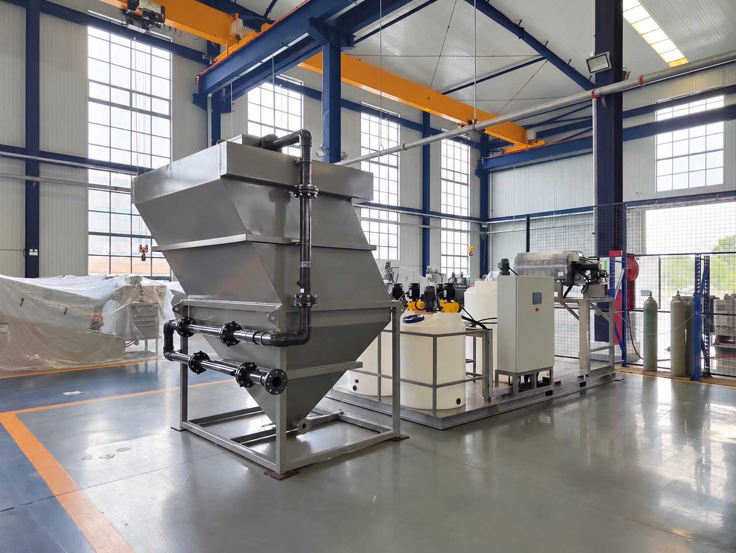
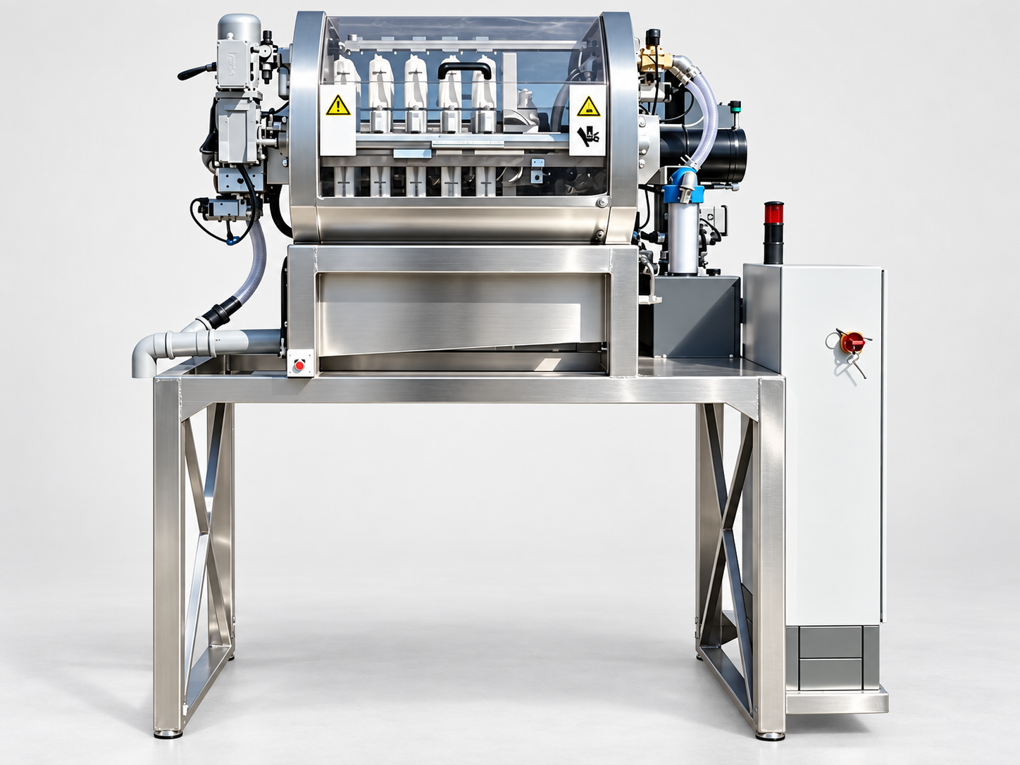
Photos are for reference of appearance and configuration. Partial enlargements are displayed from the same image. It does not indicate individual delivery results or standard delivery scope.